Improving Direct Lighting Material Occlusion - Part 1
 |
|---|
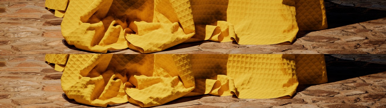
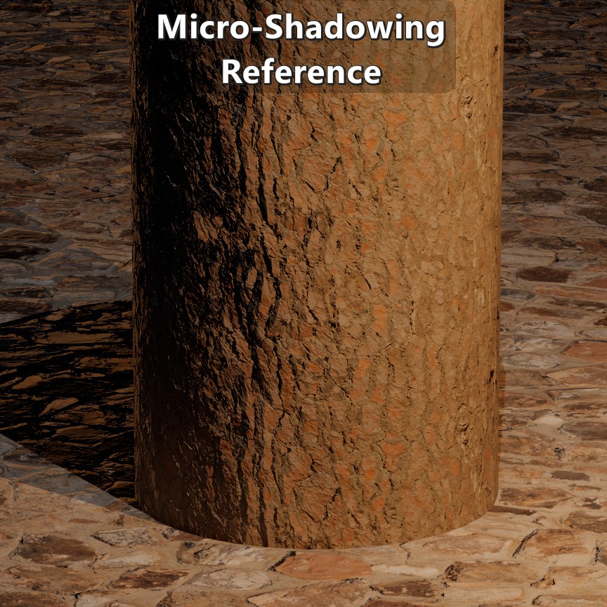
| Piqué fabric with micro-occlusion on the top, and micro-shadowing at the bottom. Both are using the same micro-occlusion map. |
Geometry virtualization and displacement systems like Nanite has allowed us to substantially increase the geometry resolution. But when it comes to representing small details like cavities, cracks, and creases, those types of solutions are too expensive to be used systemically in a game for a current generation console. As long as we have to rely on normal maps to encode geometric detail there will be a need to handle direct lighting occlusion at the mesoscopic scale. To do that most engines have relied on baking micro-occlusion onto textures or buffers. While that workaround is better than nothing, it results in a flat representation of those small details. In this series of posts I’ll touch on the issues with micro-occlusion and look at micro-shadowing as an improvement.
NOTE: This is focused specifically on material-level direct lighting occlusion and not in broader-scale indirect lighting occlusion such as what’s usually captured via screen-space or raytraced ambient occlusion.
Comparison Scene
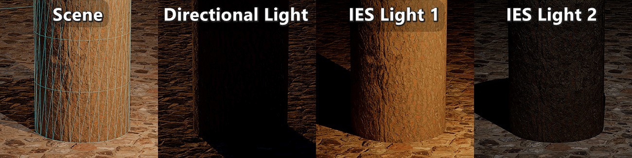
To have a basic baseline for comparisons I made an extremely simple scene that consists of a cylinder with a tree bark texture set, a flat plane with a rock wall texture set, a direction light source, and two punctual lights with an IES profile.
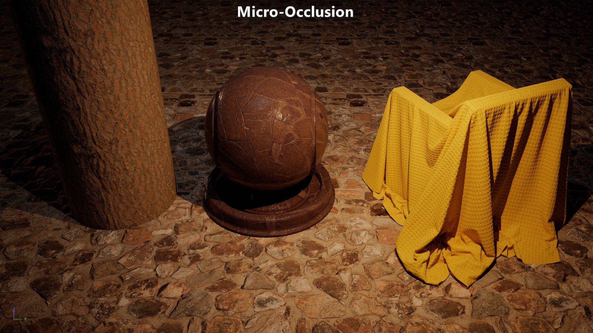
Micro-Occlusion
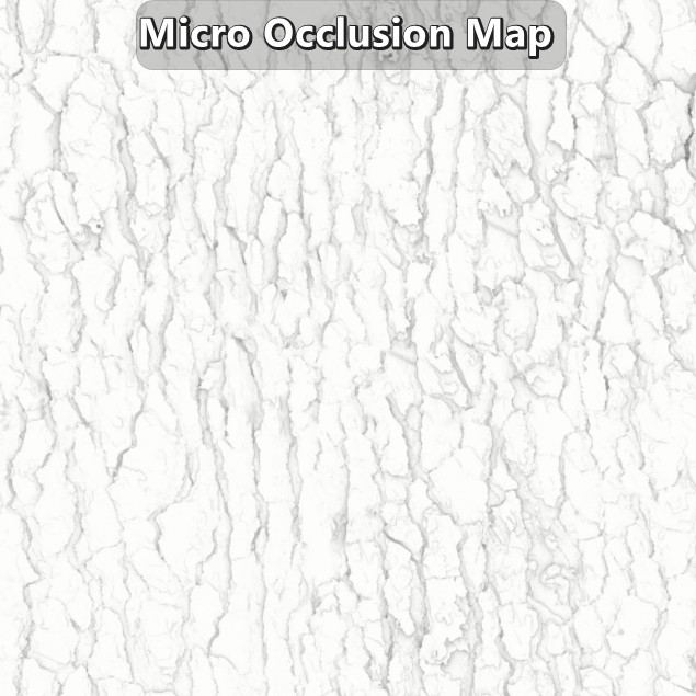
When it comes to geometry encoded in normal maps, the most common solution is to handle the direct lighting occlusion by baking or applying that occlusion onto existing maps or buffers. That means that a micro-occlusion map must be created, which is basically a material ambient occlusion (AO) bake of the high-resolution mesh with a short ray length. How short the ray length should be dependents on how much normal information is encoded in actual in-game geometry versus how much comes from the normal map. If your high-resolution mesh is that of a tree’s bark, and your in-game mesh is just a cylinder with flat faces, then the tendency will be to have a longer ray length to show occlusion that would be lost otherwise. But if the geometry is fairly similar, then the ray length can be shorter as geometry or depth data can be leveraged by other ambient occlusion and shadowing techniques.
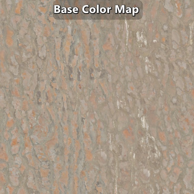
Since the occlusion needs to be applied on the diffuse and specular component, they are applied on the base color and reflectance/specularity maps respectively. Just like there isn’t a fixed ray length to generate the micro-occlusion map, there isn’t a fixed way to apply it. In most cases it doesn’t deviate much from a multiplication of the values, but it isn’t rare to see more complex approaches.
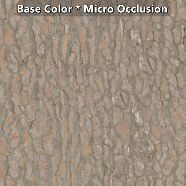 |
|---|
| Example of a tree bark texture set by Dimitrios Savva applied on a flat plane. |
The lambert diffuse BRDF is not view dependent. Due to that the pre-multiplication of the micro-occlusion with the base color is deemed to be a good enough solution, but that’s not enough for specular. Materials at \(F_{90}\) converge to 1 which means that at a grazing angle the specular response will be clearly visible. To work around that, the Schlick approximation is modified based on the assumption that no relevant real-world material has a reflectance lower than 2%. With that assumption in place the Fresnel reflectance is reduced as the reflectance value goes below 2% to the point where the specular response is completely gone.
\[{F_{0}+\left( F_{90}-F_{0} \right)\left( 1 - V\cdot H \right)^{5}}\newline {F_{0}+\left( clamp(50\mspace{2mu} F_{0},0,1)-F_{0} \right)\left( 1 - V\cdot H \right)^{5}}\]1float3 F_Schlick(in float3 F0, in float3 F90, in float VdotH)
2{
3 return F0 + (F90 - F0) * pow(1.0f - VdotH, 5.0f);
4}
5
6float3 F_SchlickF0WithMicroOcclusion(in float3 F0, in float VdotH)
7{
8 return F_Schlick(F0, saturate(50.0f * F0), VdotH);
9}
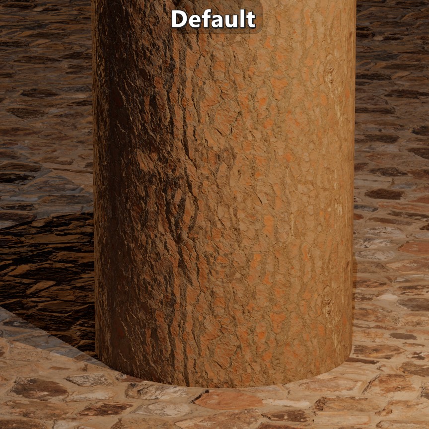
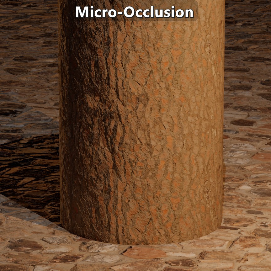 |
|---|
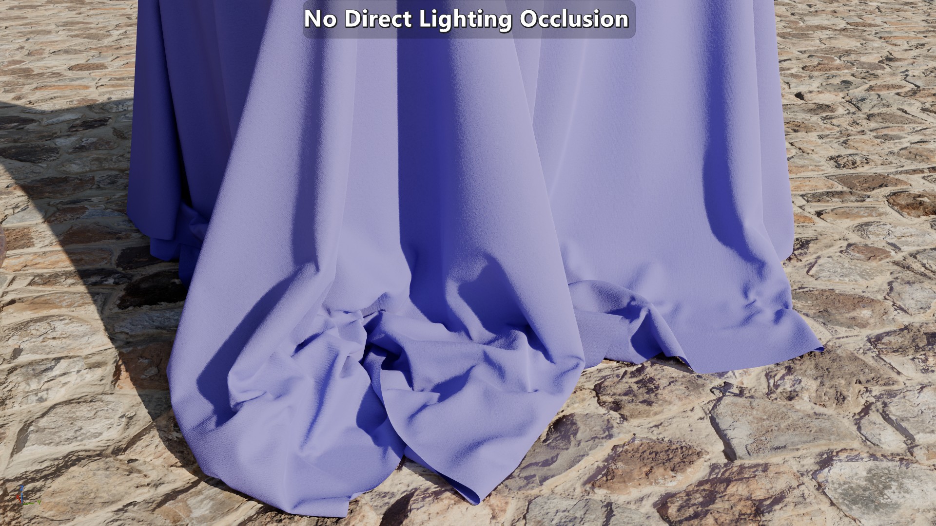
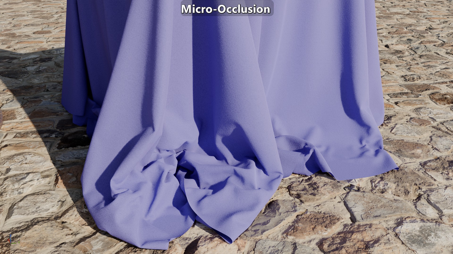
| Visual results on the comparison scene. |
The micro-occlusion approach has been documented by Frostbite (see section 4.10.3) and Unreal. It has worked well enough for indirect lighting, but the results under direct lighting are pretty flat. While the normal map will change the surface response to lighting, all the geometry baked onto the normal map wouldn’t occlude any of the direct lighting in a way that relates to the direction of the light. Looking at the same tree bark example, a light on top of a crease wouldn’t light up the crease, and a light to the side wouldn’t get occluded inside the crease either. This approach also changes the fundamental properties of the material. In the creases the base color doesn’t represent diffuse albedo anymore affecting the indirect bounces, and the reflectance isn’t representative inside the creases either giving them an ambient look. And another issue with the approach is that there is no consistency to how micro-occlusion is applied which makes the frame less coherent reducing immersion.
Possible Solutions
There are multiple approaches to deal with direct lighting material occlusion that make different trade-offs in terms of quality, memory and performance. Horizon Mapping can produce nice shadows, but it requires 8 floats per normal map texel, besides what’s necessary for the actual normal map. Normal Mapping Shadows (NMS) (demo) doesn’t require any additional maps but the quality depends on the sample count. Screen Space Shadows can also be made to handle this case, but it requires introducing a depth offset which might disable Early-Z (unless you can use semantics like SV_DepthGreater and SV_DepthLessEqual), or writing the offset to a separate gbuffer, and then tracing those buffers. Solutions like these introduce a significant cost per light since they are bandwidth-heavy and involve ray marching. Compared to those solutions, the usual micro-occlusion approach is extremely cheap, which is why it is so widely used. But depending on your context, micro-shadowing might be a reasonable alternative to micro-occlusion while being much cheaper than the previously mentioned solutions.
Micro-Shadowing
Waylon Brinck, et al. 2016 “Technical Art of Uncharted 4” presents a micro-shadowing term as a solution to the struggle their artists were facing on their transition to physically based rendering. Their intention was to derive a term from regular baked ambient occlusion that would affect not only indirect lighting but direct lighting as well. On their 2016 presentation they mentioned that since the ambient occlusion term approximates the cone angle visible from a point, then they could shadow the incoming light by comparing half that cone angle and \({N\cdot L}\).
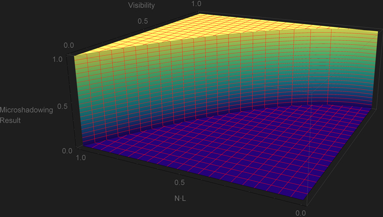
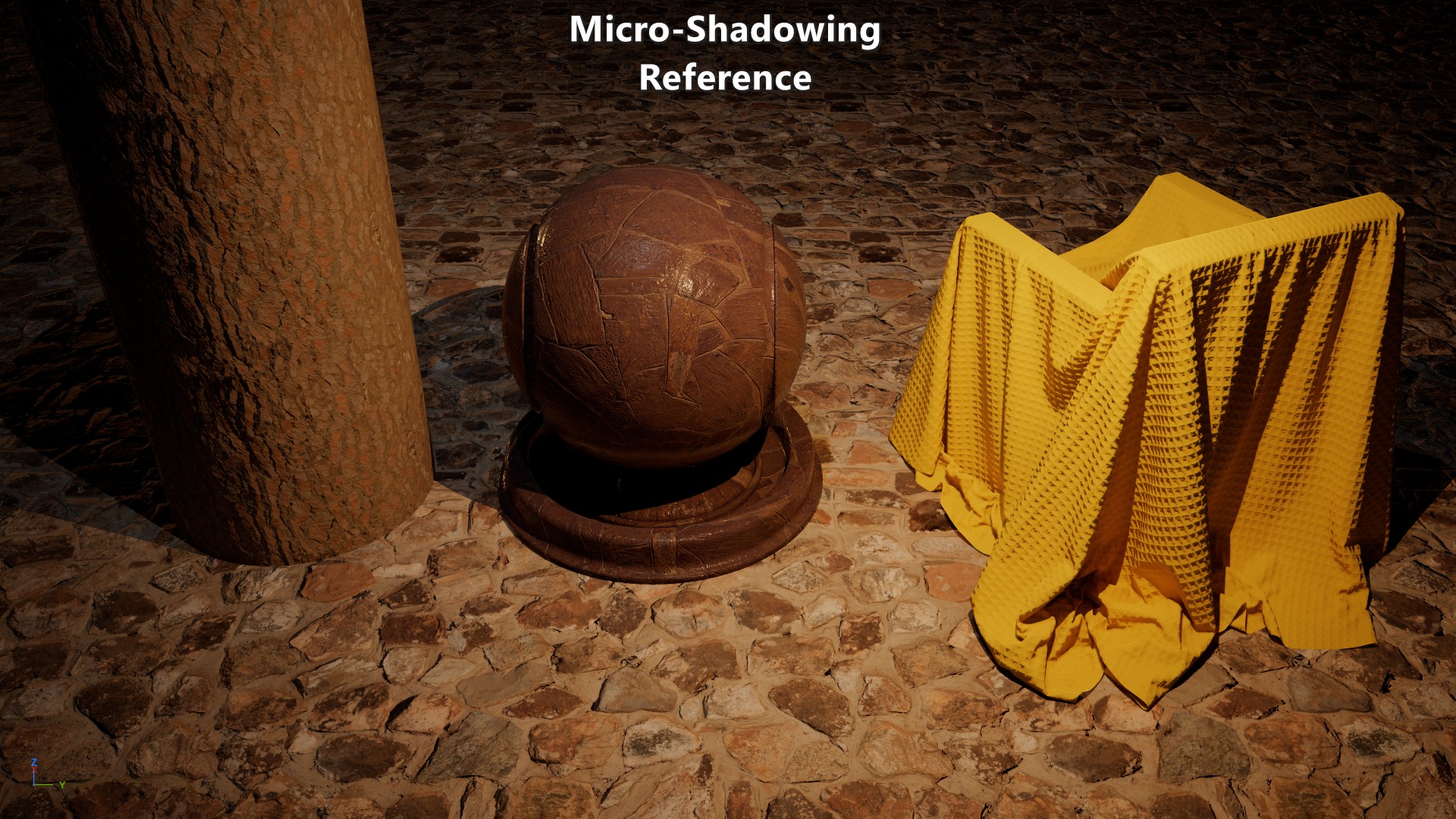
Reference Implementation
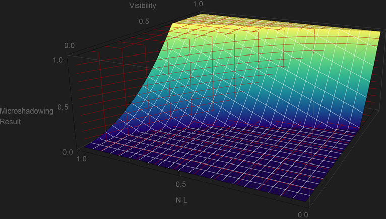
Jorge Jiménez, et al. 2016 “Practical Realtime Strategies for Accurate Indirect Occlusion” equation 18 provides the analytical expression to go from the ambient occlusion \(Visibility\) term the cosine of the cone angle \({cos\,\theta}\). Based on it we can shadow a light by comparing \({cos\,\theta}\) and \({N\cdot L}\). A normal-oriented cone isn’t a great approximation of the directional visibility, but despite that we can assume that this is our “reference” result. This is the HLSL implementation and plot of the function:
\[{cos\,\theta = \sqrt{1-Visibility}}\]\[\begin{equation} \begin{cases} 1 & \text{if}\ cos\,\theta \lt N\cdot L \\ 0 & \text{otherwise.} \end{cases} \end{equation}\]1float MicroShadowingTermReference(in float visibility, in float NdotL)
2{
3 const float cosTheta = sqrt(1.0f - visibility);
4 return step(cosTheta, NdotL);
5}
 |
|---|
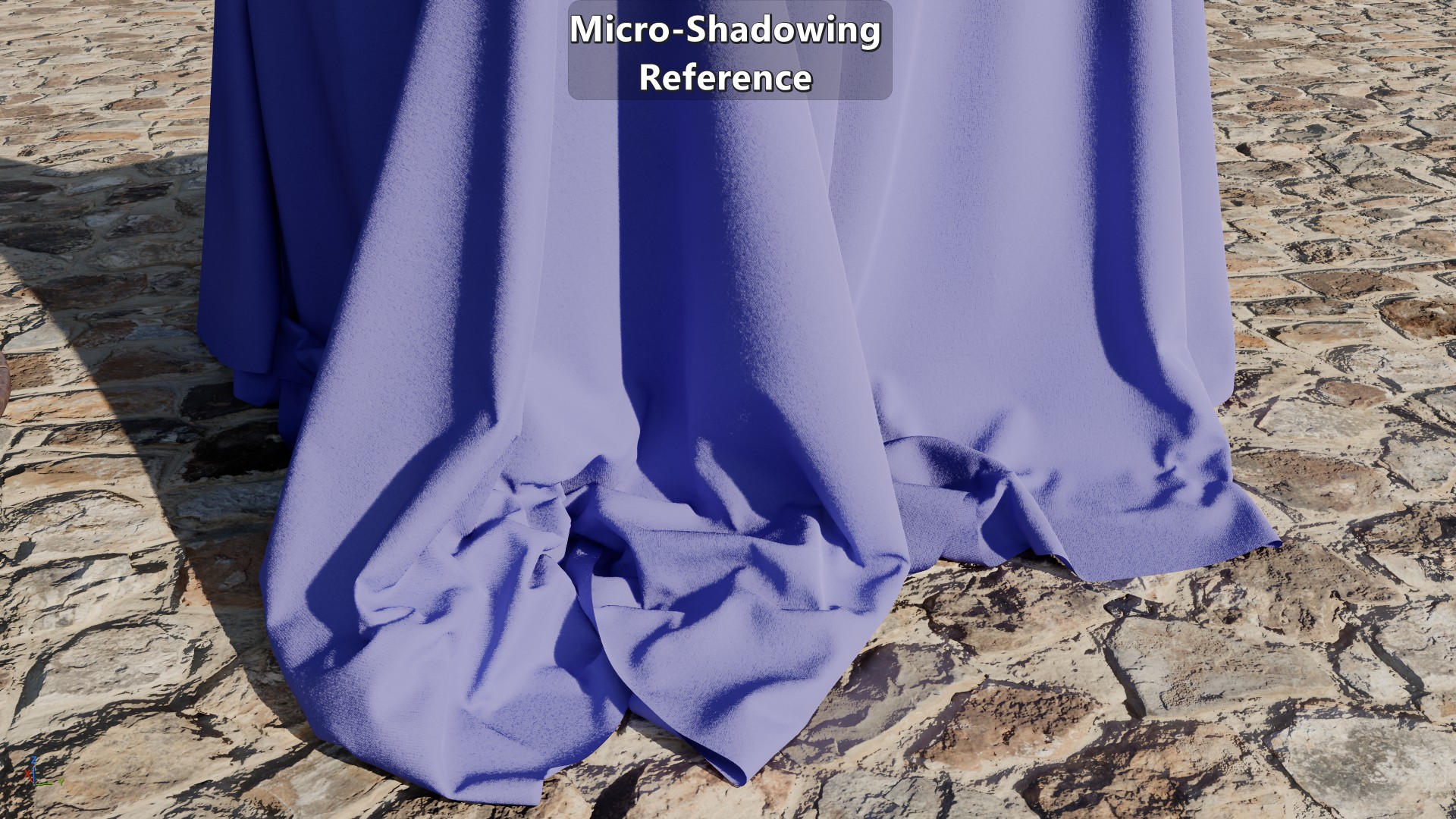
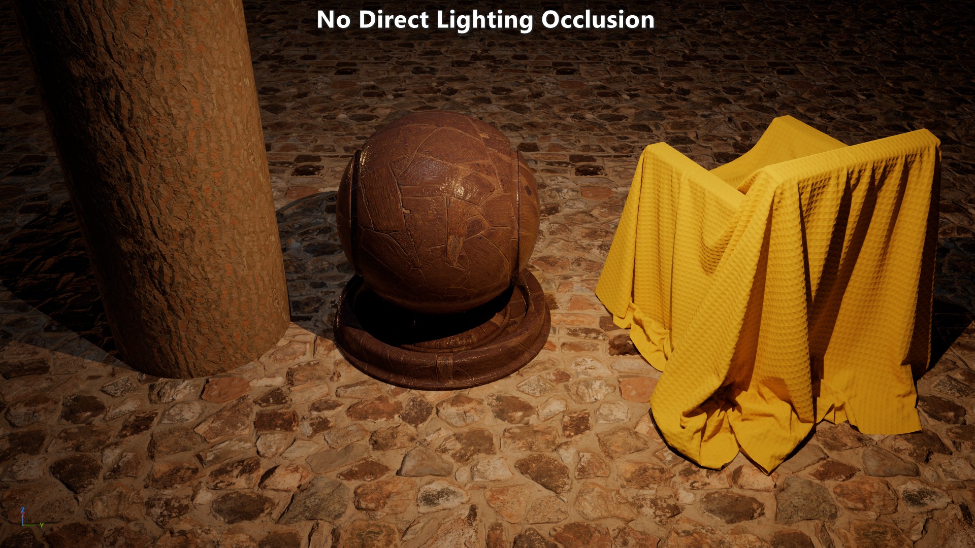
| Visual results in comparison to no occlusion. NOTE: after clicking on a screenshot you can use the keyboard arrow keys to toggle between them. |
Looking at the function and plot it is obvious that every pixel goes sharply from fully in light to fully in shadows, but it still provides a reference for that boundary. Of course the visual comparison itself shows that sharp transition.
One relevant assumption of the \(Visibility\) term is that the ambient occlusion bake was generated with samples that are cosine weighted. That’s usually the case, but tools like Substance and Marmoset allow for bakes with uniform weighted samples. If that’s the case then:
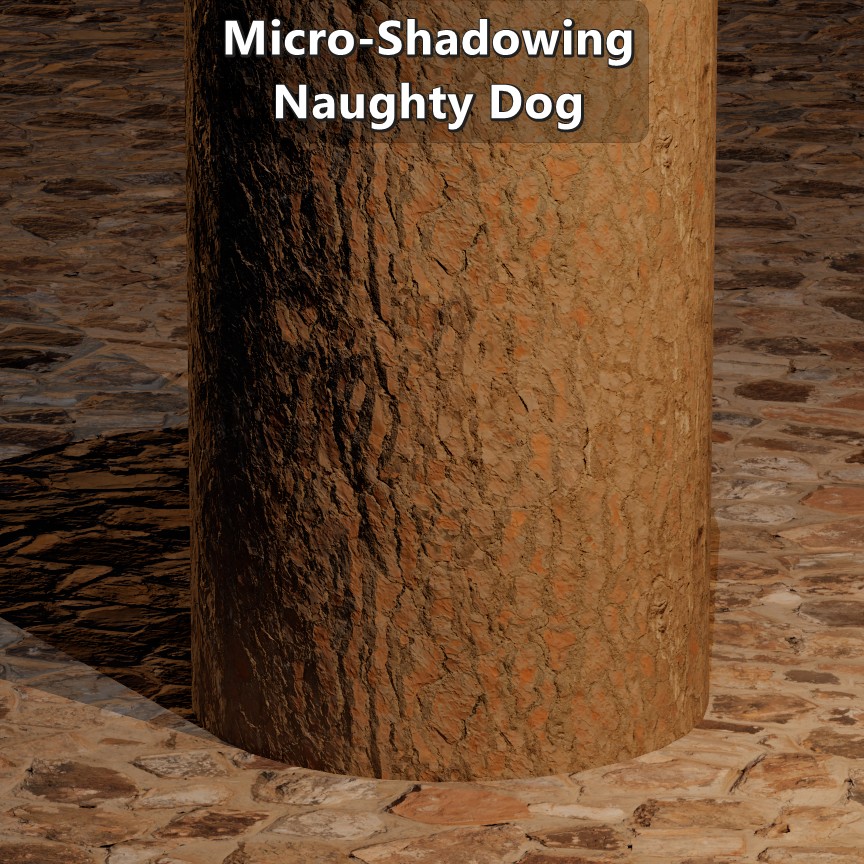
\[{cos\,\theta = {1-Visibility}}\]Naughty Dog’s Approach
On their presentation they make it clear that their solution was more artistic than technical, and that they were dealing with ambient occlusion maps that were not authored consistently. So their solution boils down to
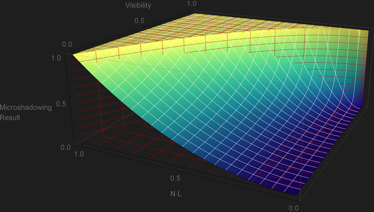
\[{clamp\left( N\cdot L + 2\ Visibility^{2} - 1,\, 0, 1\right)}\]1float MicroShadowingTermNaughtyDog(in float visibility, in float NdotL)
2{
3 const float aperture = 2.0f * visibility * visibility;
4 return saturate(NdotL + aperture - 1.0f);
5}
The plot shows a fair amount of over and under occlusion that doesn’t follow the boundary of the cone. But that’s not as negative as it may seem at first sight as it retains some good properties. As previously mentioned, a binary transition from in-light to in-shadows is not desirable as that’s only representative of a perfectly smooth surface, and this approach doesn’t suffer that issue. That particular property reflects the artistical nature of the approach. The other good property is that when \({Visibility=0}\) the light would be fully shadowed. Unfortunately it also has issues. For any \(Visibility\) value below \(\sqrt{\frac{1}{2}}\) the light starts to get micro shadowed even though the light can be fully aligned with the normal, and it doesn’t get fully shadowed for any light direction when the \(Visibility\) value is above \(\sqrt{\frac{1}{2}}\).
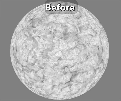
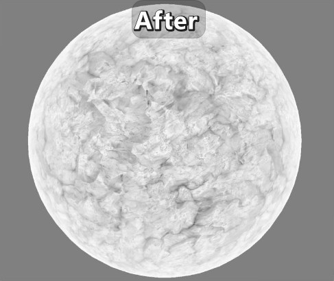
On their paper they also made a relevant observation that cavities can get occluded at grazing angles so they introduced “AO Fresnel” to fade out the occlusion specifically on surfaces with baked lighting:
\[{lerp\left( x,y,s \right)=x + s(y-x)}\\ {Visibility=lerp\left( 1, Visibility, clamp\left(N\cdot V, 0, 1\right) \right)}\]1float VisibilityFadeNaughtyDog(in float visibility, in float3 vertexN, in float3 V)
2{
3 const float aoFadeTerm = saturate(dot(vertexN, V));
4 return lerp(1.0f, visibility, aoFadeTerm);
5}
 |
|---|
| Before and after applying “AO Fresnel”. Screenshots from Naughty Dog’s presentation. |
Since in their presentation they mention that “AO Fresnel” isn’t applied across the board, let’s look at the results without it:
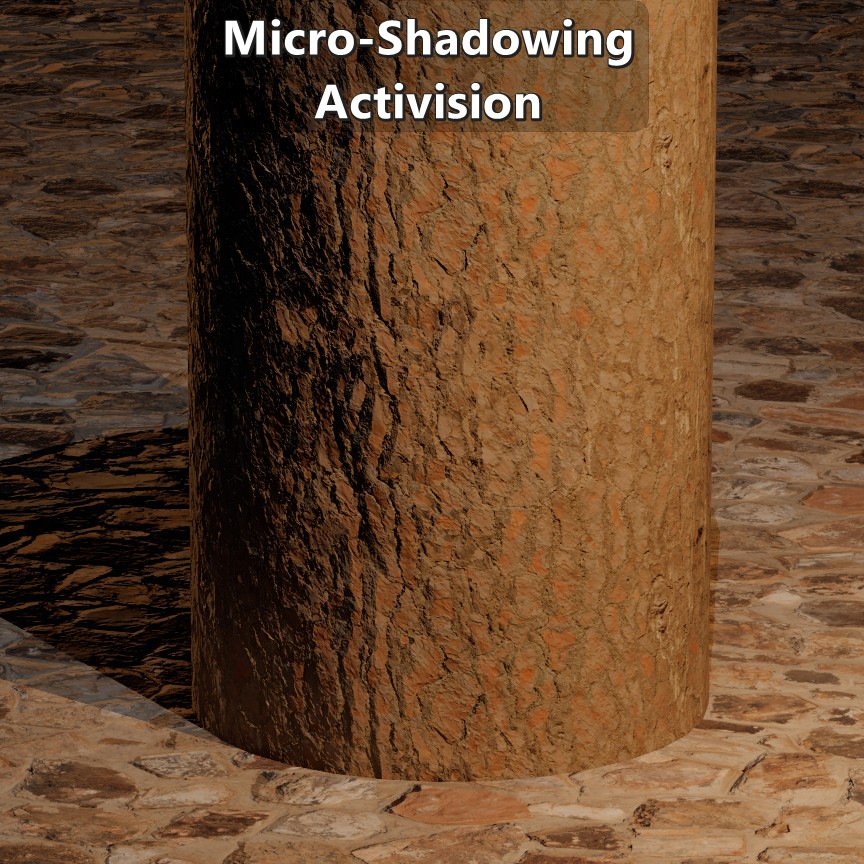
Activision’s Approach
Danny Chan, 2018 “Material Advances in Call of Duty: WWII” goes over how they generate an ambient occlusion map from a normal map, and how they did direct lighting material occlusion. Given the binary nature of the reference function, on their presentation they decided to apply an ad hoc falloff following a scaled \({N\cdot L}\) factor from the edge of the cone to 90 degrees.
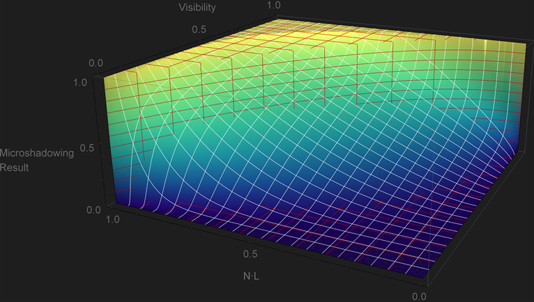
\[{clamp\left(\frac{N\cdot L}{cos\,\theta}, 0, 1 \right)^{2}}\] 1float MicroShadowingTermActivision(in float visibility, in float NdotL)
2{
3 // Avoid division by 0.
4 if (visibility == 1.0f)
5 return 1.0f;
6
7 const float cosTheta = sqrt(1.0f - visibility);
8 const float result = saturate(NdotL / cosTheta);
9 return result * result;
10}
This solution has the property that it follows the reference function, but it shows a lot of under-occlusion. In particular, it is problematic that a light will still be visible even when \({Visibility=0}\). This would limit the artists when it comes to representing tight cavities such as skin pores. But despite that, the fact that it follows the reference function makes it a good starting point for an alternative.
Similarly to Naughty Dog’s approach, this paper also presents an adjustment to \({cos\,\theta}\). In this case it is based on \({N\cdot V}\) and \(Roughness\) such that there is no micro-shadowing at grazing angles or low roughness. Below is the code as provided in the paper with a minor modification to use roughness instead of gloss:
\[{lerp\left( x,y,s \right)=x + s(y-x)}\\ {lerp\left( 0,cos\,\theta, {\left( {1 - clamp\left(1.5(1-Roughness), 0, 1 \right)^{8}} \right)\left( 1 - \left( {1-{N\cdot V}} \right)^{4} \right)} \right)}\] 1float AdjustCosConeAngle(float cosConeAngle, float gloss, float NdotV)
2{
3 // The cone is an especially poor approximation to actual visibility for high gloss values.
4 // This is an ad hoc adjustment.
5 // Gloss above 0.67 is unaffected by the cone, i.e.\ we set to full cone angle.
6 gloss = saturate(gloss * 1.5); // Optionally, omit this line.
7 float gloss2 = gloss * gloss;
8 float gloss4 = gloss2 * gloss2;
9 float gloss8 = gloss4 * gloss4;
10 float oneMinusNdotV2 = (1 - NdotV) * (1 - NdotV);
11 float oneMinusNdotV4 = oneMinusNdotV2 * oneMinusNdotV2;
12 // We lerp towards full cone angle based on gloss and NdotV .
13 cosConeAngle = lerp(0, cosConeAngle, (1 - gloss8) * (1 - oneMinusNdotV4));
14 return cosConeAngle;
15}
16
17float GetVisibilityFromMaterialOcclusion(float materialOcclusion, float roughness, float NdotV, const float3 worldNormal, const float3 lightDir)
18{
19 float gloss = 1 - roughness; // NOTE: line not included in the paper.
20 float NdotL = dot(worldNormal.xyz, lightDir.xyz);
21 float vis = materialOcclusion;
22 float cosConeAngle = sqrt(1 - vis);
23 float adjustedCosConeAngle = AdjustCosConeAngle(cosConeAngle, gloss, NdotV);
24 adjustedCosConeAngle = max(adjustedCosConeAngle, 0.001);
25 vis = saturate(NdotL / adjustedCosConeAngle);
26 return vis * vis;
27}
There are a couple of things worth noting about this adjustment to \({cos\,\theta}\). First is that the for any \({Roughness\le 0.33}\) there isn’t any micro-shadowing at all. The second one is that the \(Roughness\) term has the non-standard parametrization for GGX shown below:
\[{\alpha=\sqrt{\frac{2}{1+2^{18(1-Roughness)}}}}\]
 |
|---|
| Visual results. |
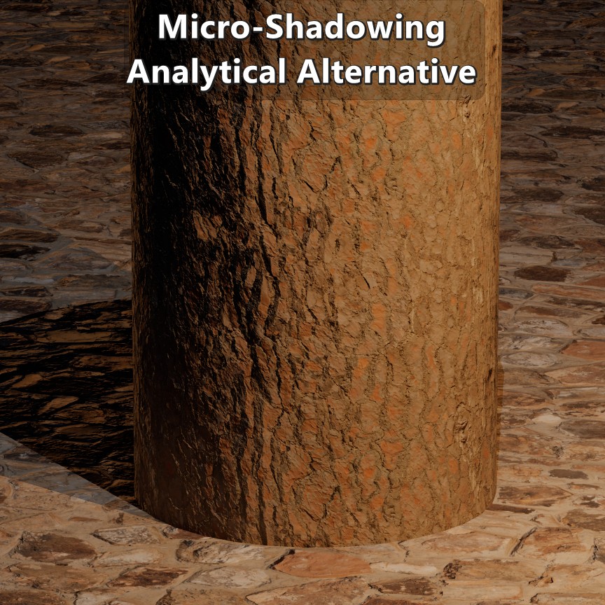
Analytical Alternative
As mentioned before, Activision’s approach is a good starting point for an alternative. Their approach is split between a micro-shadowing function that isn’t binary, and an adjustment to \({cos\,\theta}\) to reduce the micro-shadowing at grazing angles. But, is there a simple function that could be a reasonable compromise between over and under occlusion without adjustments?
Given the plot of Activision’s approach, as \(Visibility\) decreases the micro-shadowing result gets further away from the reference. But the bigger the exponent the tighter it fits. That means that we could uses an exponent based on the reciprocal of \(Visibility\). The other relevant factor is that following the exact boundary of the reference implementation becomes less relevant the more the pixel diviates away from a perfectly smooth surface. That means that we’ll want to reduce the area of the plot where a pixel is fully unoccluded, while still making sure that it is fully unoccluded when \({Visibility=1}\), and fully occluded when \({Visibility=0}\).
To do that we can define \({cos\,\theta'}\) where the \(Visibility\) can be elevated to an integer exponent greater than one. That will tweak the boundary where a pixel is fully unoccluded. And the ramp down to full micro-shadowing can be tweaked by multiplying the reciprocal of \(Visibility\) by a constant less than one. Given the ad hoc nature of this approach you could tweak this any way you like, but this is what I ended up with:
\[{cos\,\theta' = \sqrt{1-Visibility^{5}}\\[5pt]} {clamp\left(\frac{N\cdot L}{cos\,\theta'}, 0, 1\right)^{\LARGE \frac{0.75}{Visibility}}}\] 1float pow5(float x)
2{
3 float xx = x * x;
4 return xx * xx * x;
5}
6
7float MicroShadowingTermPZAnalytical(in float visibility, in float NdotL)
8{
9 // Avoid divisions by 0.
10 if (frac(visibility) == 0.0f)
11 return visibility;
12
13 const float cosThetaPrime = sqrt(1.0f - pow5(visibility));
14 return pow(saturate(NdotL / cosThetaPrime), 0.75f * rcp(visibility));
15}
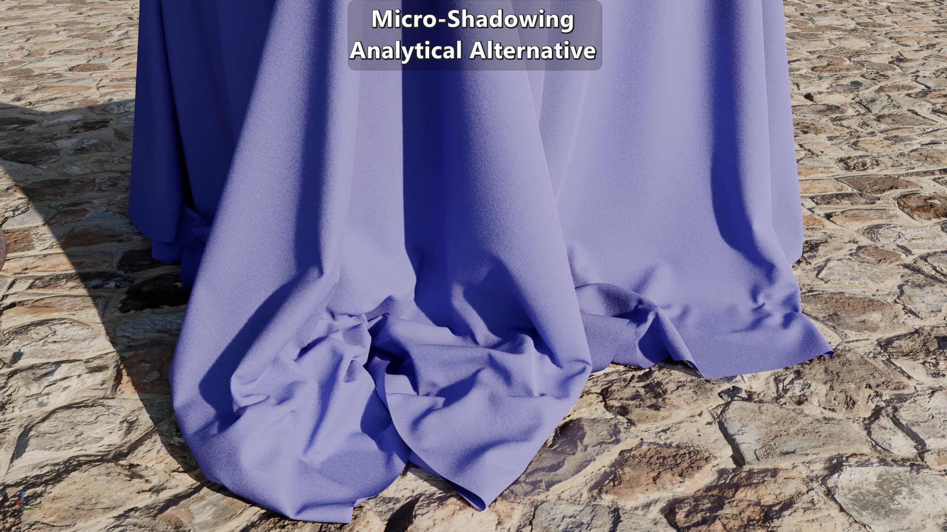
 This approach tries to keep a reasonable amount of under-occlusion without decreasing it too fast, while at the same time making sure that the zero and full \(Visibility\) case are handled. This approach is more expensive than Naughty Dog’s and Activision’s due to the use of quarter-rate instructions. But with that said, this isn’t as problematic in current generation consoles since non-trascendental instructions can be executed in parallel which helps hide the cost. At the same time, any calculations related to \(Visibility\) don’t have to be done per light which also reduces the cost. Naughty Dog’s and Activision’s approaches were done for their previous-generation titles so it isn’t surprising that they avoided an implementation like this one.
 |
|---|
| Visual results. |
Next Time
All the previous approaches have one thing in common, none of them have a concrete link to the actual micro surface. Except for the adjustment of \({cos\,\theta}\) in Activision’s approach, none of them are roughness-aware, and none of them change depending on how the micro surface is defined. A micro surface defined as microfacets isn’t the same as one defined as microcylinders, and their arrangement also makes a big difference. On the next post I’ll be going into an alternative approach to micro-shadowing based on a micro-surface.
Results
Multiple Materials


Knitted Fleece