Physically Based Content
While it has been over a decade since the sea-change towards physically based rendering (PBR) started, it isn’t rare to find that artists and engineers still have certain challenges when it comes to PBR. Some concepts are hard to grasp, and the trade-offs being made to fulfill artistic objectives are usually misunderstood. Over the years I have had the chance to work on the implementation of PBR on multiple engines used in AAA games, as well as working on games that used PBR engines. That meant that I had the responsibility of helping artists and engineers understand how to work within that context, so I thought it would be a good idea to share some of that experience.
While there is a consensus on the relevance of PBR from a technical point of view, the physically based approach to content creation doesn’t have the same level of consensus. I have worked with material artists that clearly understand each parameter of a given definition of a PBR surface, while I have also worked with material artists that assumed that the content was PBR just by the nature of using a PBR engine. On the lighting side I have worked with lighters that clearly understand the lighting units, the interaction of light with the surfaces, and the relevance of exposure, while other ones tweaked values until they saw the results they wanted to see. The intention with this post is to shed some light (pun intended) on the relevance of physically based content and some pointers on how to do that.
Assumptions.
This post will be based on a few assumptions that dictate the requirements for the content and quality. Many of the things that will be mentioned on the post will not seem as relevant as stated if the requirements were different.
- Your game is grounded in reality. While stylized games often use PBR (such as Overwatch), there is no real definition on how to make content for them as it all depends on the style.
- Your game isn’t mostly based on indoor environments. Games that are fundamentally indoor don’t struggle as much with content because everything is more controlled, so inconsistencies are not as visible. Dead Space remake is an example of a game that was mostly indoor environments.
- Dynamic time of day is essential to your game. When you don’t have time of day as a factor, then some of the struggles with content are reduced because the dynamic range of the scene is smaller. For example, in Dragon Age: The Veilguard a lot of the content could be tuned to the initial lighting condition reducing the challenges (which doesn’t mean it is easy).
- Your game modifies, reuses, and releases new content on a regular basis. When you have to keep making modification and releasing new content, then a lot of the assumptions that you could make about the use of the content and the context where that content is placed essentially don’t hold up.
- Your content is meant to be at the quality level of a AAA game. Most of the recommendations assume that there is a high-level of craftsmanship and attention to detail necessary, and where only assembling content from asset libraries (such as Megascans or Substance) isn’t enough. Outside that context many of the recommendations might seem too complicated, too expensive, or not impactful enough.
Physically based geometry.
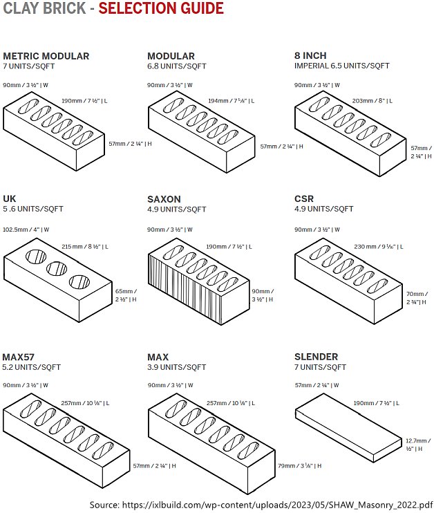
Most people don’t think of geometry as being relevant to PBR as the focus is usually placed on materials. But having the geometry be grounded on reality is fundamental to have consistent result when content is assembled, and it is fundamental to the lighting of a scene. When your geometry isn’t physically based then you struggle with the composition of the scene, the lighting of it, and even material parameters. Let’s assume an artist is making a house with exposed brick walls. The first challenge artists hit is the scale and tiling of the bricks, specially if the game supports both first person and third person cameras. The artist might be pleased with the result on the first-person camera, but then they switch to a third person camera and they realize that each brick is too big or too small compared to the character. But if they source physical information of the brick they want to create, then they will be hitting the right scale from the get-go, and that allows that geometry to be placed anywhere and remain consistent in both first-person and third-person views.
 |
|---|
| Brick size information from a Canadian brick manufacturer Shaw Brick. |
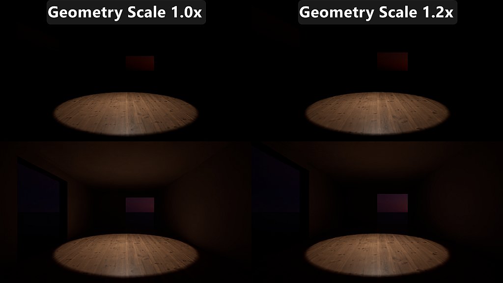
There is one personal experience that comes to mind related to the geometry scale impact on lighting. Years ago, I was working on an indoor sport game and I was the main rendering engineer focused on lighting and materials. The roof of one of the stadiums never looked quite right and it was more expensive in terms of performance than many of the stadiums that seemed more complex. When I took a look I found some lights that were added to boost up the indirect bounce on the roof and upper stands. When I disabled those lights, performance increased but those areas looked too dim even though the lighting values at the playing surface were matching real life illuminance measurements. Eventually the stadium had to be updated due to authenticity requirements and the stadium was laser scanned. And that’s when we found out that the old geometry was incorrect, and the roof was quite a few meters away from the playing surface compared to the stadium in real life. That caused the indirect bounces to dim down before arriving on the roof which then also affected subsequent bounces.
 |
|---|
| Effect of geometry scale on lighting. Top row excludes indirect lighting and bottom row includes it. Note the change in the brightness of the roof. |
The next issue is that the geometry scale can affect the material parameters, specially when it comes to albedo and subsurface scattering parameters. On the albedo front I have seen multiple instances of lighters asking for albedo changes because areas under indirect lighting looked too dim or too bright when the issue was the scale of the geometry. Subsurface scattering parameters are especially sensitive to geometry scale, as in real life we get cues on the size of certain objects based on the subsurface scattering. If the artists don’t keep geometry scales based on physical values, then odds are that a bunch of time will be spent setting up subsurface scattering profiles per object.

 |
|---|
| Bigger and smaller object with size conveyed by subsurface scattering. |
Physically based materials.
There are is so much written about this that I’ll just be touching on relevant tools and processes. Ideally you would scan full materials with a specialized scanner or build your own scanner. But most studios don’t have central teams that have the tools or time available for that. Because of that I’m going to be talking about tools and processes that are reasonable to implement in most AAA studios.
Base color.
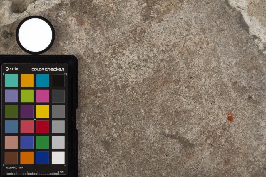
This is known as diffuse albedo when talking about dielectrics, or as specular color when talking about conductors. For a scalable and portable approach to capture diffuse albedo you should rely on cross-polarized photography. That allows the blocking of specular reflections since that light specularly reflected remains polarized and it gets blocked by the filter on the lens. Make sure that your photos include a ColorChecker for color correction, and a 99% reflectance Spectralon that you can color pick to use to use as a divisor for the whole image so that everything ends up in the right albedo range. The paring of the 99% Spectralon with the 2% Spectralon is also useful to ensure that your exposure bracketing captured the whole range necessary, and also to reference when capturing low diffuse albedo surfaces like asphalt. Another relevant item when you are not using a material scanning device (or you are not making your own) or don’t have a fully controlled light condition is to have a powerful flash. A powerful flash will allow you to keep the camera at its native ISO and with a narrow aperture, while at the same time reducing the impact of non-polarized outside lighting in the final frame.
 |
|---|
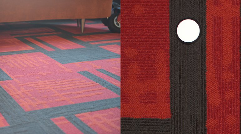
| Examples of processed diffuse albedo captures. Note the perfectly white Spectralon disk. The second picture shows the carpet being captured on its left side, and the diffuse albedo on the right side. |
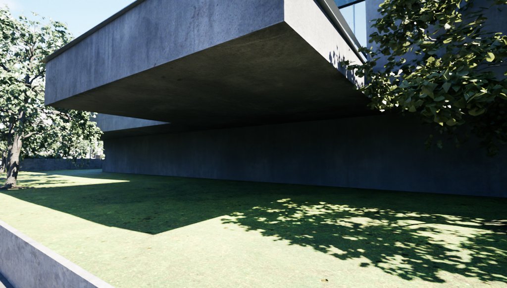
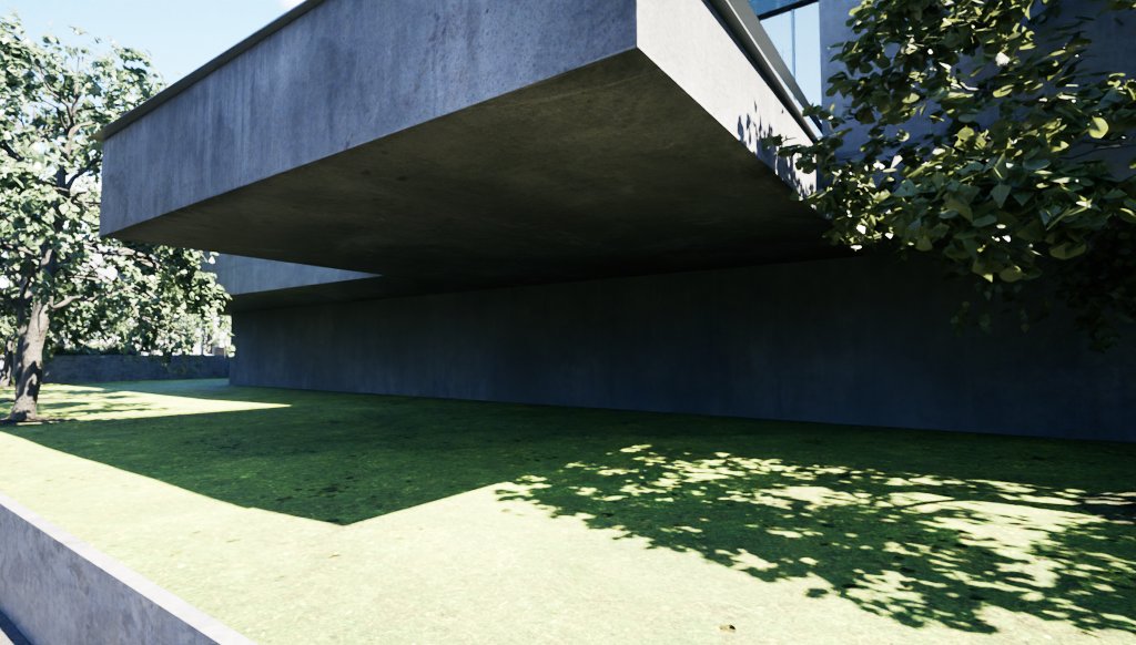
One of the reasons why it is so important to try to have physically based albedo values is that it has a big effect on lighting. A diffuse albedo texture that seems reasonable when placed on a sphere lit by an HDRI can substantially affect the look of a scene once it is placed in a level. This can eventually lead to lighters making bad decisions such as trying to solve the issues by scaling the indirect bounces.
 |
|---|
| Small change in the grass diffuse albedo texture producing a more visible light bounce. |
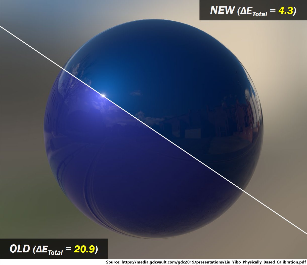
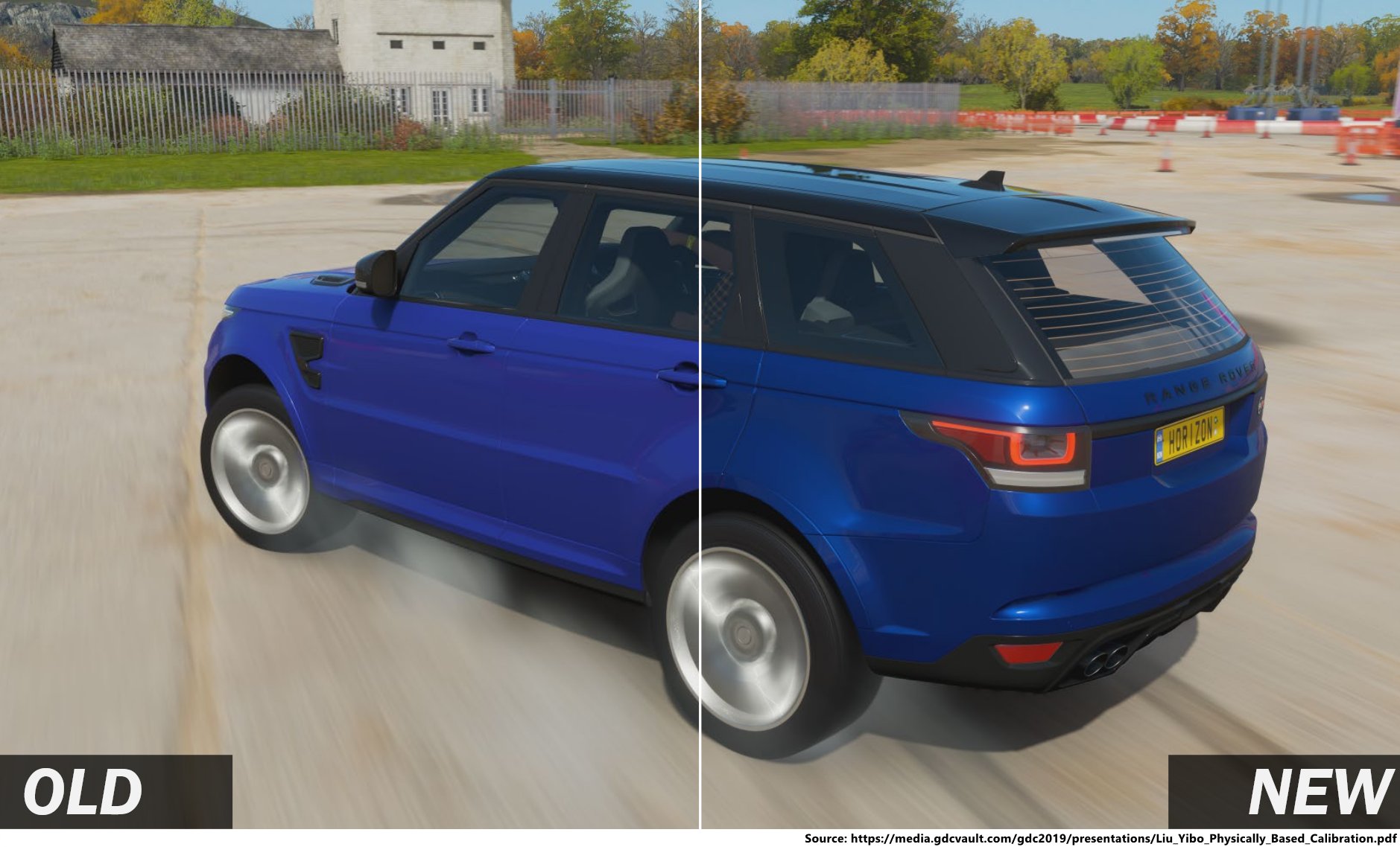
For conductors the work is a bit different. Many common metals have values you can use from common databases. For more specialized cases like metallic car paints the use of a multi-angle spectrophotometer is recommended if you need accurate representation of them. Note that when you don’t have measurements, then odds are that materials quality will suffer because it is specially challenging to hit proper specular color values out of photos.
 |
|---|
| Comparison of car paint material handmade by artist and one based on measured data. |
In almost every studio I’ve worked for there was a time when an artist wanted to discuss what’s the lowest acceptable diffuse albedo when it came to base color validation. If you have a good capture pipeline than includes the 2% Spectralon the discussion gets easier, but if you don’t then it can be quite complicated. While coatings like Vantablack can be used to justify going to the lowest values, that’s an exceptional material. But often the issue was the lack of understanding of the impact of roughness and the lighting conditions on the appearance of low diffuse albedo materials. In a white furnace a material with different roughness should look the same, but on any non-uniform lighting condition it will look different as seen in the example below.
 |
|---|
| Physical sample in a regular meeting room lighting condition showing the same Munsell N1 color swatch in decreasing roughness. Note how the color seems to get darker as smoothness increases. |
Metalness.
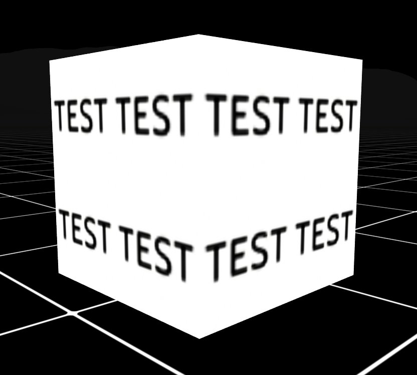
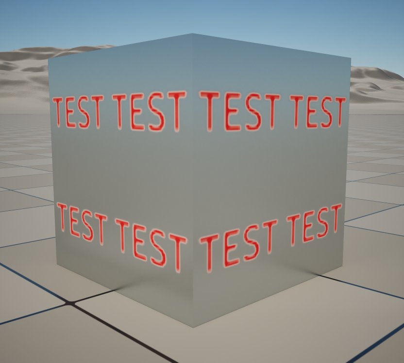
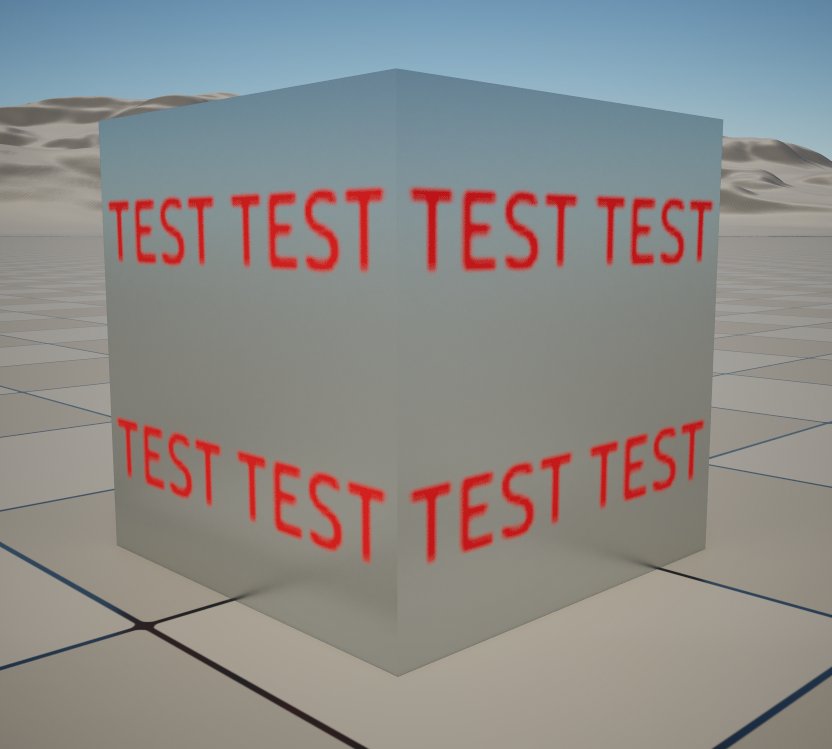
This is an important value because it determines if the pixel is treated as a dielectric or as a conductor. The Frostbite Engine calls it Metal Mask to convey the fact that it meant to be either 0 or 1. The challenge for artists comes when a surface needs a transition from a dielectric to a metal, the common case being chipped paint on top of a metallic surface. When a pixel ends up having a metalnness value that isn’t 0 or 1, then that pixel will end up somewhere in the range of reflectance of a semiconductor which is often not intended. Those will often show up as a bright outline on the transition. To solve the issue, I’ve successfully used FastNoise to do a 1-bit dither which is spatiotemporally stable.
 |
|---|
| FastNoise used to 1-bit dither metalness and avoid a semiconductor outline between the dielectric text and the base conductor surface. |
Reflectance or specular.
The reflectance or specular value only applies to dielectrics, and it is one of the values that is either left unmodified from a 4% reference value, or it is authored incorrectly. There are multiple reasons for why this has been challenging:
- Hard to source data ready to use. Except for some databases which have at least an index of refraction (IOR) value available, a fair level of technical expertise is necessary to source and interpret other data available. For example, if an artist needs to make a asphalt road, sourcing a reflectance value involves looking at a relevant paper (for example “Characterization of stripping properties of stone material in asphalt” by Lyne et al), looking at the index of refraction of the different minerals and the bitumen, come up with a range of values, and convert those to a reflectance or specular value that the engine can use.
- Non-standardized parametrization. Depending on the engine the reflectance values are parametrized differently. Unreal Engine specular values go from 0% to 8% linearly, but other engines have other parametrizations. For example, Frostbite has reflectance remapped so 0.5 represent 4% reflectance and 1.0 represents 16%. In practical terms that allows Unreal to represent reflectance of materials like sapphire, while Frostbite its able to represent reflectance up to the value of diamond.
- Perceived limited relevance of the value. Because getting plausible reflectance values can be so challenging, one of the issues is that the impact of the reflectance when looked on an object lit by an HDRI might seem minor and not worth the effort. The impact seems even less relevant if previewed with auto exposure.
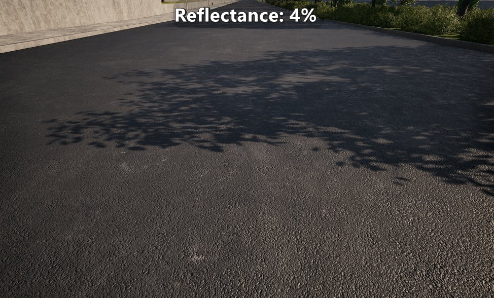
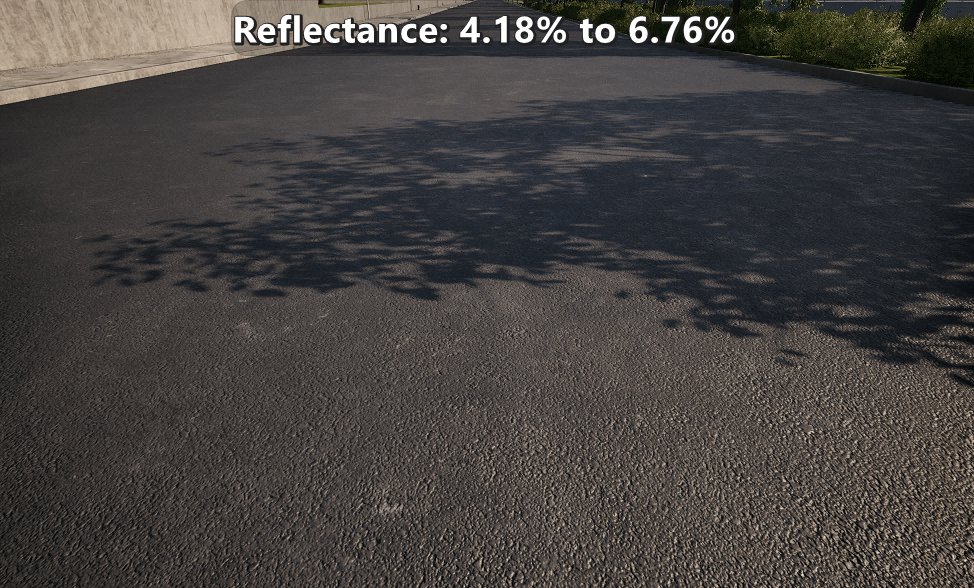
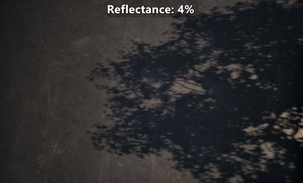
I do think that reflectance is one of the parameters that separates a good or great material from an acceptable one. Studios often make material libraries, and spending some time to come up with plausible reflectance values for most core materials in your game can make a difference in the overall frame. When you want to see the relevance of having plausible reflectance values, don’t just look at the material on its own lit by an HDRI, also look at it in context. That will often help you get a better sense of the relevance, and it will also help you see if the overall reflectance of the materials in the scene are making sense.
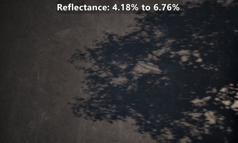 |
|---|
| Comparison of reflectance for fresh asphalt between default 4% and values sourced from a paper. |
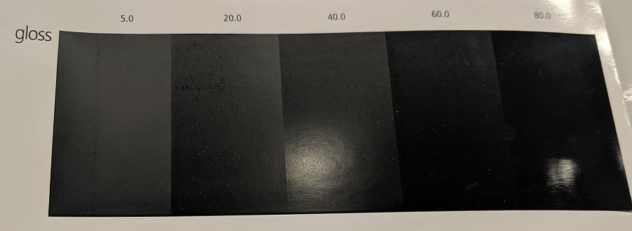
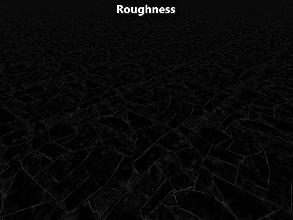
Roughness.
This parameter is one of the most artistic ones because different engines parametrize roughness in different ways, and because there isn’t a known mapping to convert the gloss units of a glossmeter into the roughness value of an engine. But usually the biggest challenges comes when the artists are trying to have a material well represented up close and far away. The issue is that with a traditional setup, as normal map and roughness maps get mipmapped, then the material loses its normal detail, and the roughness tends to reduce as values get averaged. That makes it so a bumpy somewhat smooth surface up close looks flat and very smooth far away as if the surface was wet at a distance. To combat that artists compromise on the content up close and far away. They do that by adding more complexity to the material shader (such as increasing the roughness by hand at a distance) and having odd approaches to the creation of roughness maps such as using curvature information as a source.
To author roughness properly the first step is understanding that the normal maps and roughness maps represents geometric information at different scales. Normal maps represent geometry at a mesoscopic scale and up, while roughness maps represents geometry at the microscopic scale as microfacet normal distributions.
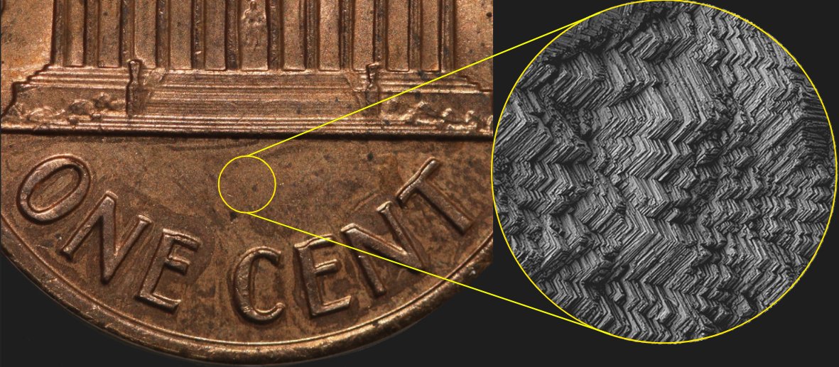 |
|---|
| Coin at the geometry and normal map scale on the left, and at 2500x magnification showing what would be represented by a roughness map. |
Given that, in my experience the optimal approach is to have artists author normal and roughness maps up close. They should author pretty flat roughness maps instead of coming up with odd roughness values derived from curvature or anything else. But they should be able to rely on technical approaches to retain the desired appearance at a distance or at grazing angles.
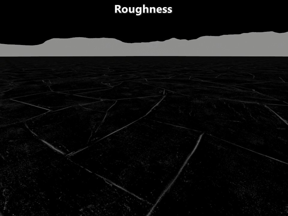
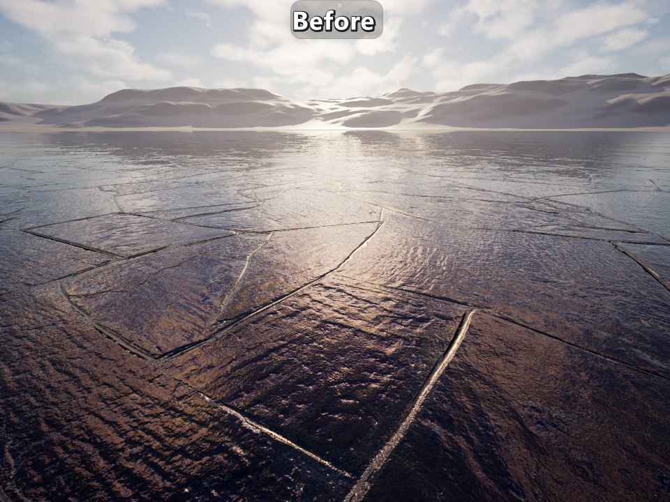
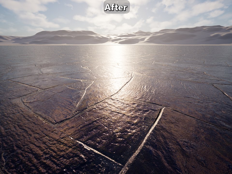
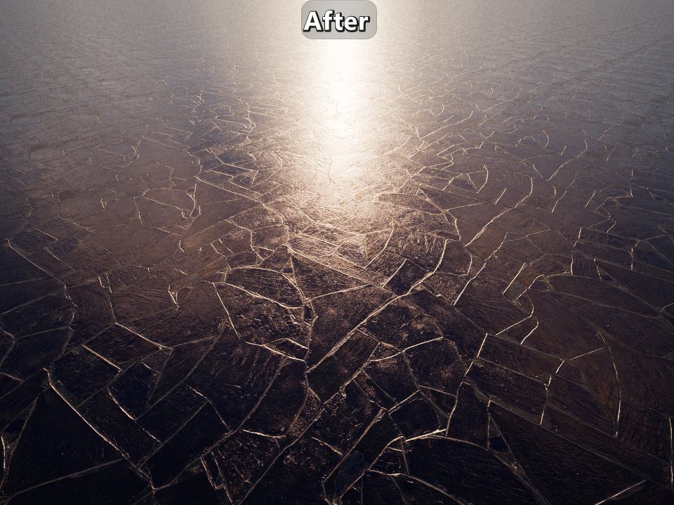 |
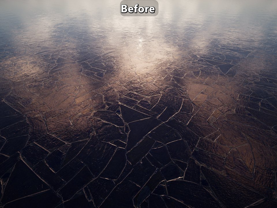
|---|
| Overly smooth slate floor texture set before and after filtering the Normal Distribution Function (NDF) to preserve the appearance. |
Emissive material setup.
Emissive materials are at the intersection of the work of material artists and lighting artists. Emissive surfaces are handled in different ways in different engines, and it is also highly dependent on the lighting solutions being used for diffuse and specular. From a materials artist point of view, their work should be to setup the non-HDR emissive color, and they should provide lighters with an emissive intensity parameter for lighters to control. Avoid any use of any multiplier based on exposure (also known as eye adaptation) in the setup. While it is tempting for artists to use that to have a consistent reproduction of the color of the emissive and for the initial intensity setup, that consistency is highly problematic when your materials are assumed to be reused in different lighting conditions. So just like materials should be physically based, so should be the lighting setup, and that includes emissive materials.
 |
|---|
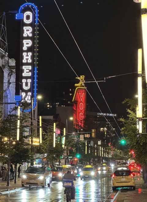
| Street signs in Vancouver where maximum allowed luminance is 300 nits at night and 5000 nits during the day. |
Physically based lighting.
Often the lighting setup is not physically based. Instead, it is setup artistically where issues are worked around as they show up. Why is that problematic? After all, you can achieve the same looking frame at different exposure just by tweaking the lights and emissive intensities. The issue is that it is very hard to land on a flexible setup with immersive plausible visual results if the lighting and exposure setup is not physically based. If that sounds familiar, it’s because it was the same reason that justified the transition to physically based materials in the industry. Just like you can get a good-looking final frame with non-PBR materials, you can get a good-looking frame with non-PBR lighting and exposure setup. The issue is that it becomes very difficult to do that when you can’t rely on the knowledge of lights in real life, or even photography knowledge (such as the sunny 16 rule).
Lighting units.
Understanding of lighting units and how to measure lighting is fundamental knowledge for lighters. Lighters that have a good understanding of those aspects are the ones that usually get to the best results faster. Lighting involves a whole set of different lighting concepts and units, and their impact is not easy to understand.
There are radiometric and photometric quantities, each with their own set of units. The fundamental difference is that photometry is focused on measuring light as perceived by the human eye. The human eye is only able to perceive a limited band of electromagnetic radiation, and the human eye is not equally sensitive to all the wavelengths within that band. The focus on this post will be on photometric quantities as that’s what’s common in real time rendering with the only notable exception I’m aware of being Blender’s EEVEE.
Depending on the type of light, there will be different set of quantities and units available. The relevant light types are:
- Directional light. This is usually used for the sun or moon light. They are assumed to be infinitely far away, have no falloff, and they usually provide an angular diameter parameter.
- Punctual lights. Any light that has a position in the world and doesn’t have an area. That includes point lights, spot lights, and even line lights.
- Area lights. Any light that has a position in the world and has an area. That includes sphere lights, disk lights, tube lights, etc.
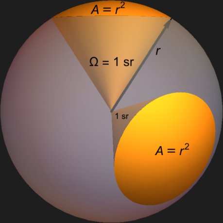
Now we can get into the specific quantities and units, and that’s where less technical lighters struggle. In general they assume that the different lighting quantities and units are all the same and apply the same on all lights. They seem similar, but they are different in a similar way mass and weight are different. The first couple of relevant units are the candela and the lumen. The candela represents luminous intensity, and it measures the perceived emitted power per unit solid angle. The lumen represents luminous flux and it measures the perceived emitted power in all directions. Looking at the diagram below, the candela measures the perceived emitted power over the spherical cap of the unit solid angle, while the lumen measures the perceived emitted power over the whole unit sphere.
 |
|---|
| Solid angle (omega) of one steradian with a radius of one. There are 4π steradians in a sphere. |
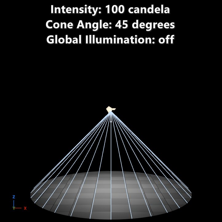
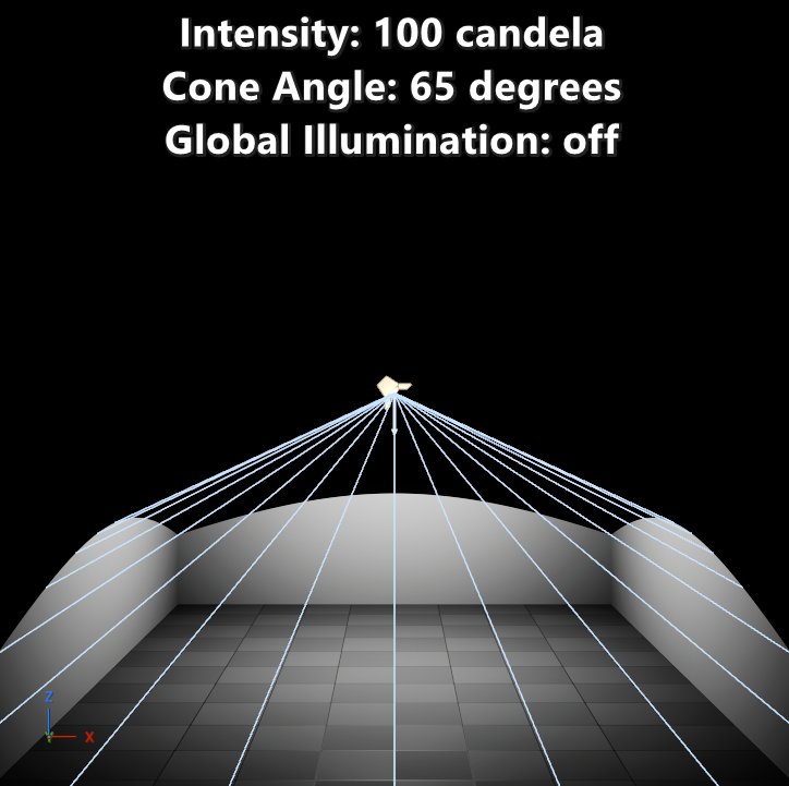
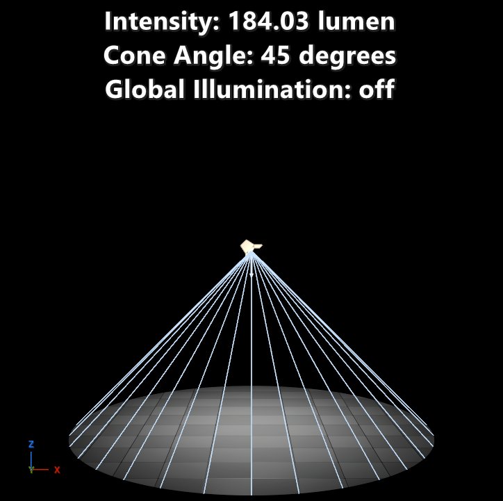
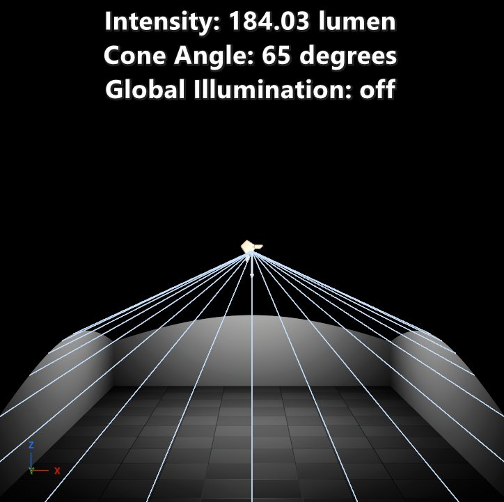
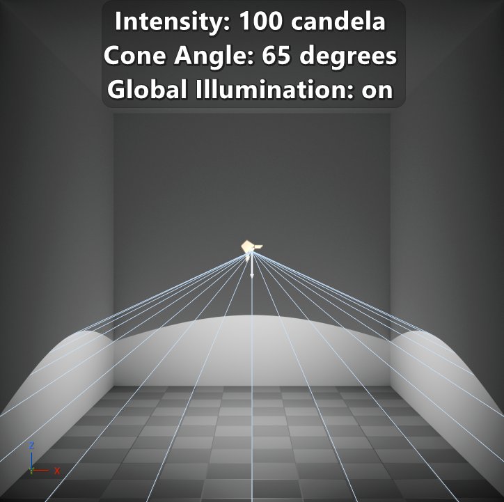
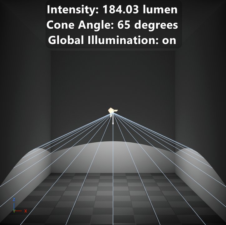
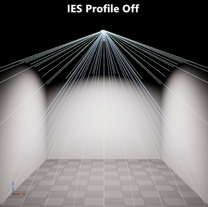
Point lights are simple to understand when it comes to representing the intensity in candela or lumens, and that’s because the solid angle is fixed to be 4π steradians. But the change comes with spotlights as the cone angle of emission is controlled by the artist. Because the candela represents the intensity per unit solid angle, then no matter what’s the cone angle of the spotlight the intensity will remain the same. But with lumens that’s different. Since a lumen represents intensity in all directions, as the cone angle of the spotlight gets smaller the perceived intensity of the light increases since all the power going in all directions is getting focused onto that cone angle as seen in the screenshots below. This means that the conversion from lumen to candela and vice versa requires the solid angle for the conversion. You will usually (if not always) find light bulbs mention the number of lumens in the packaging since that’s a consistent value independent of the lighting fixture.
 |
|---|
| Visible change in intensity depending on units and cone angle of the spotlight. |
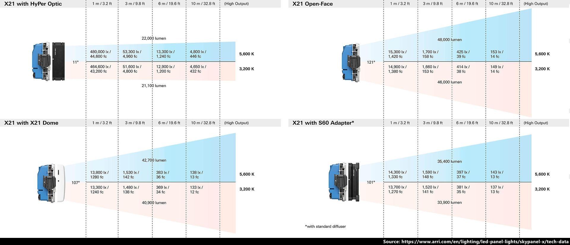
The next relevant units are the nit and the lux. The nit represents luminance, and it is equivalent to 1 candela per square meter. The lux represents illuminance, and it is equivalent to 1 lumen per square meter. Different units and quantities are used to define area lights in real life depending of what’s the use. Monitors and LED signs usually use nits as the focus is on the emitting surface. For professional lighting panels, lux at a given distance are often used. My assumption is that the use of lux in that context is to give customer values they are used to measure.
 |
|---|
| Specifications for an ARRI SkyPanel X with different accessories attached. |
In terms of behavior, if you set up a light in nits and then change the area of the light then the perceived intensity will change. When using lumens intensity will remain constant as the area of the light changes, but with nits that isn’t the case. Since nits are used in real life for things like monitors and LED signs, it is important that the geometry is physically based and that the area light is aligned to that geometry. In other scenarios using lumens makes sense.
Engines that support specifying a punctual or area light intensity based on lux are either rare or non-existent. The reason is that the distance to the emitter must be provided for the unit conversions which means that it adds an non-intuitive parameter to the lights. But with that said, the lux is the most common unit used in engines to define the intensity of a directional lights. Directional lights are often used to represent the sun, and the sun intensity in units like lumens or candelas are huge and it has a very small solid angle. But the lux value at a surface perpendicular to the sun has a reasonable scale, and it is way easier to measure.
Lighting measurement.
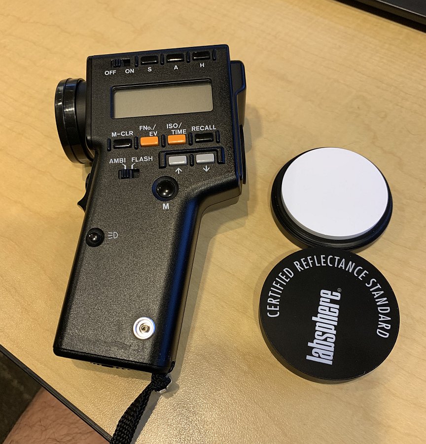
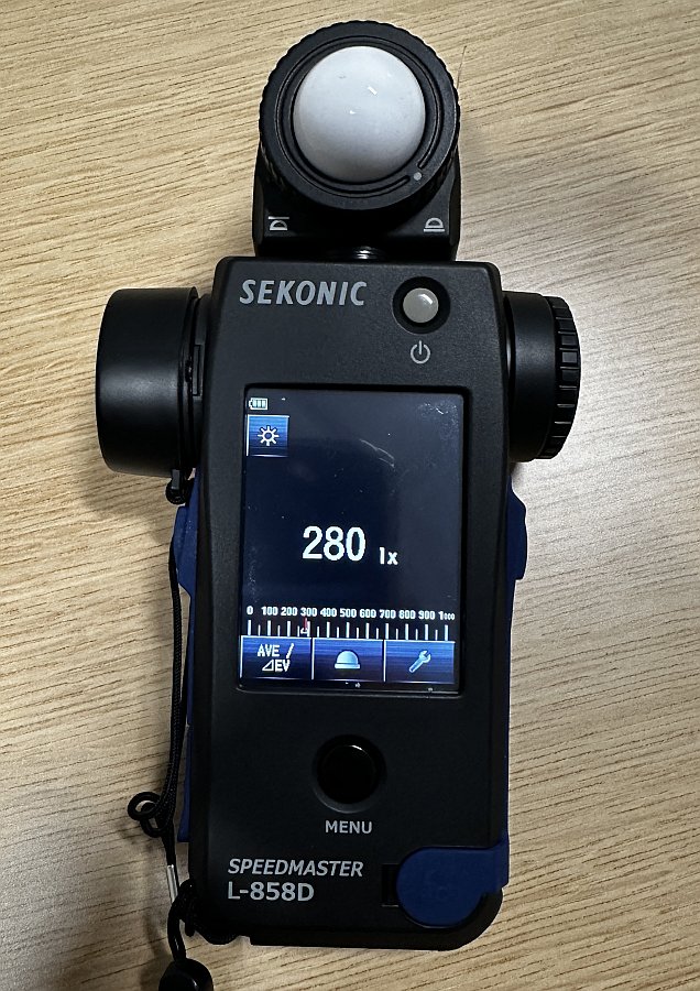
When you need to recreate a physical environment or lighting condition from real life taking pictures isn’t a solution to get matching results in engine. The tools you will need are a spot or luminance meter, and an illuminance meter. Some devices combine both meters. The illuminance meter should be setup to output lux instead of foot-candles. When you use it try to avoid casting your own shadow on the white dome of the device as that will alter the reading. The spot or luminance meter should be setup to output nits. If the meter only supports EVs (like the spot meter in the first picture below), then it should be setup with an ISO of 100 to be able to convert from EV100 to nits. The Spectralon can be useful together with the spot meter to get luminance readings that can be easy to reproduce in engine.
 |
|---|
| Spot meter, Spectralon, and spot + illuminance meter. |
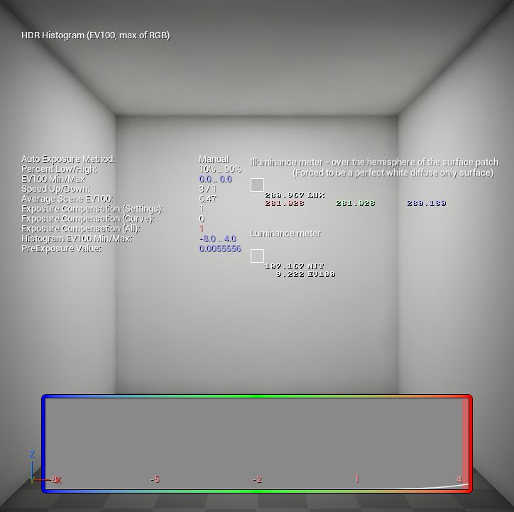
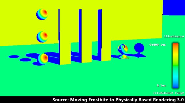
PBR engines usually provide equivalent tools to measure illuminance and luminance in engine, but be aware that exposure might impact the reading. Having absolute values in lighting buffers is too expensive in terms of memory and bandwidth since not even 16-bit floats per component are enough to represent real world luminance values. To deal with that engines often pre-expose the values based on the exposure of previous frames since overexposed values are not relevant for the final frame. But what that means is that the values read from the lighting buffers can be clamped to the exposure. To make sure you get a good reading you will have to check that whatever you are trying to measure isn’t overexposed.
 |
|---|
| Illuminance and luminance meter in Unreal Engine, and illuminance debug view in Frostbite. |
Photometric profiles.
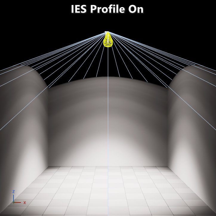
The most common and reliable source of real-world lighting data are the IES profiles. IES stands for Illuminating Engineering Society, and their IES LM-75-19 specification defines a standard method to measure and describe a light’s intensity distribution. This means that the shape and intensity of an actual real-life light is described. Most manufacturers provide IES profiles for their lights which means that the same light can used in engine. Most engines provide the option to take the intensity from the IES profile directly (with an optional scale for artistic control), or to use the regular intensity parameter of the light. It is recommended to use the intensity as provided by the IES profile without any scaling. That will ensure consistent results on engines with a correct implementation of IES profiles. Besides the benefits of having more correct intensities, IES profiles also allow for more interesting results that are hard or impossible to match with regular lights. Unfortunately, they do come at a cost since a texture needs to be sampled for every light with an IES profile assigned.
 |
|---|
| Spotlights without and with an IES profile of the ARRI Daylight 18/12 and with the same luminous flux emitted. |
Physically based camera.
Up until the beginning of the 2000s most games were doing everything in low dynamic range (LDR). For the most part there was no specular lighting, there was a single-color map that defined a material, and lighting would have a range of 0 to 1 that would be applied by multiplying it by the color map. There were very few exceptions to this (such as Quake III via “overbright bits”) which meant that everything had to be pre-exposed. But with the arrival of Direct3D 9’s Shader Model 2 doors opened to go to HDR. By the mid-2000s the transition to HDR started to take off with Valve’s Source Engine being an early adopter shipping that in their Half-Life 2: Lost Coast demo. Since then, the cameras had to get more complex to deal with that dynamic range.
But having physically based materials and lighting wouldn’t be very useful nor manageable if there is no consideration for a physically based camera. Without a physically based camera it is very difficult to achieve realistic results, and it’s difficult to leverage the photographic and cinematographic knowledge that has been built for over a hundred years. For that reason, even though it’s possible to have a very basic camera and exposure setup, it makes more sense to leverage a physically based camera.
Physically based cameras follow a similar pipeline to a digital camera. There are many steps and parameters that can be involved depending on the level of complexity and fidelity of the engine’s physical camera setup, but the most basic ones are:
- A lens with an aperture control in f-stops which defines how much luminance can make it to the sensor while the shutter is open. This also affects depth of field.
- A shutter that controls for how long sensor is exposed, controlled via a shutter speed that’s usually defined in 1/seconds. This also affects motion blur.
- A sensor’s signal gain in ISO which defines how sensitive the sensor is.
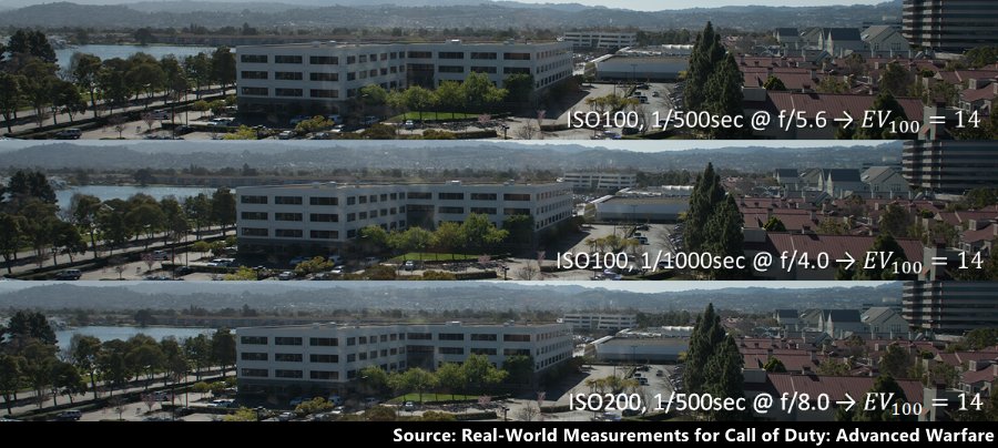
When the implementation is correct different combinations of those parameters can result in the same exposure as seen below. This means that convention around exposure values such as EV100 can be leveraged. And this also means that basic rules, such as the sunny 16 rule, can be followed in engine.
 |
|---|
| Example of different combinations of aperture, shutter speed, and ISO resulting in the same exposure. |
If the lighting setup is not physically based, then odds are that the camera parameters will also not be physically based which means that it will not be easy to land on consistent results. At the same time, if the camera parameters values are not physically based, then odds are that the lighting will not be consistent, specially in dusk scenarios where artificial lighting mixes with sun and sky lighting. That feedback loop of adjustments can become a vicious cycle. Leveraging physically based values can help you break that.
Post processing and art direction.
“How come this section doesn’t start with ‘Physically based’?” The reason is that this is the stage of the pipeline where the art direction can be executed without big detrimental downstream effects. This is the stage where the results of using physically based values can be art directed to fit the needs of the game.
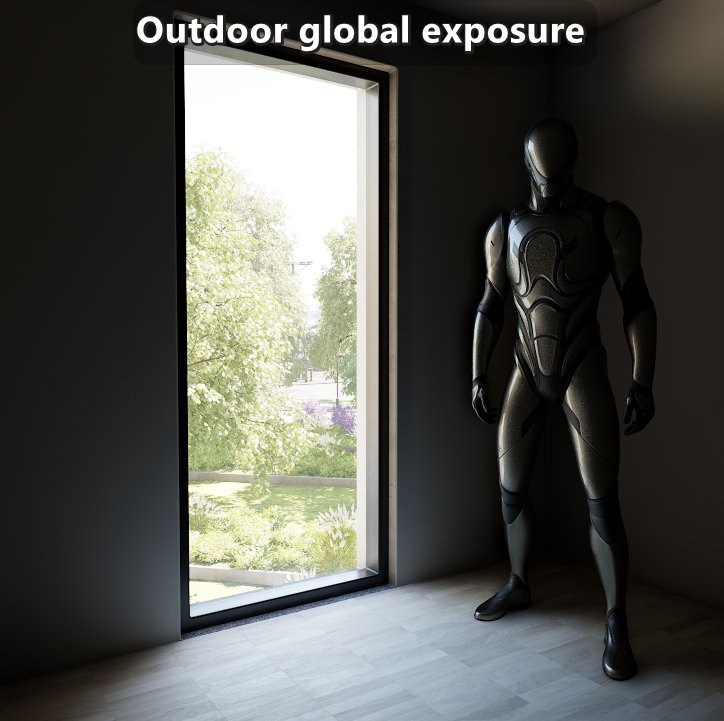
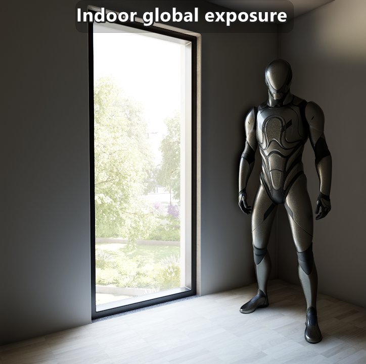
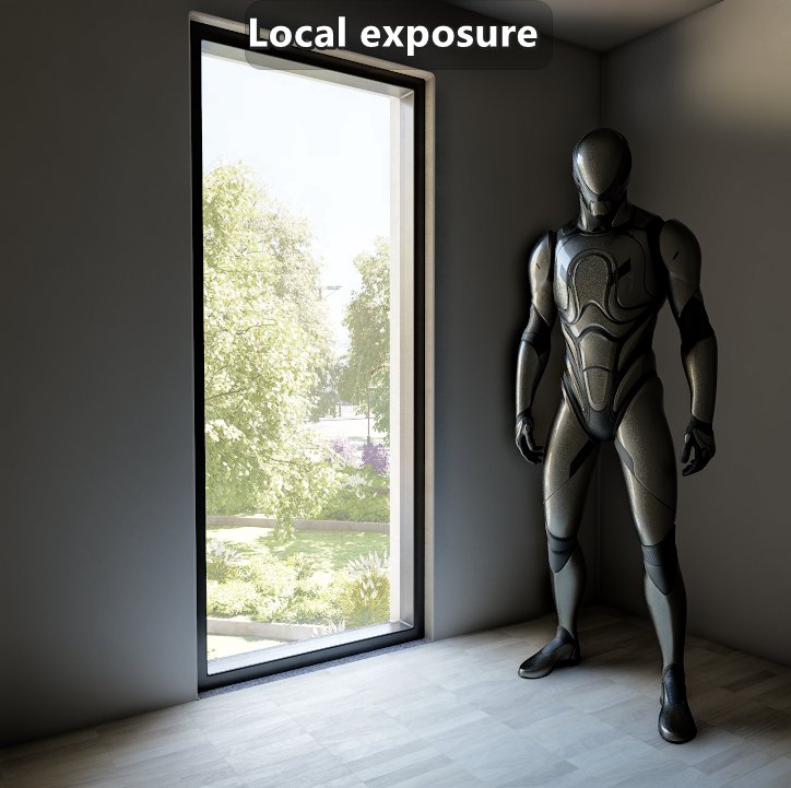
One example of that relates to exposure. If you take a picture in real life from a dark indoor towards a window in a bright sunny day, then you will be able to expose for the indoor or the outdoor. It isn’t possible to have both exposed correctly at the same time since the difference in luminance is just too big. While having the outdoors overexposed might be realistic, there needs to be some art direction to ensure readability of the outdoor for gameplay reasons. A seemingly easy fix is to reduce the intensity of the sun and sky such that the dynamic range is compressed. While that might fix that specific gameplay issue, it does that at the expense of time of day and cinematics quality. Using post effects solutions like local exposure can give you the result you want when you need them.
 |
|---|
| The outdoor lighting is way more intense than indoor. Local exposure is used to get the desired results instead of changing the intensity of the sun and sky. |
Or as another example, if the art direction calls for darker blacks, instead of changing base color maps and impacting direct and indirect lighting you can apply a color grade. That means that changing the art direction in the future (be it because you haven’t reached a final art direction or for a new season) doesn’t involve remaking or tuning base color maps. This is also the stage where the impact of physically based values such as the intensity of the sun can be art directed without changing the actual lighting.
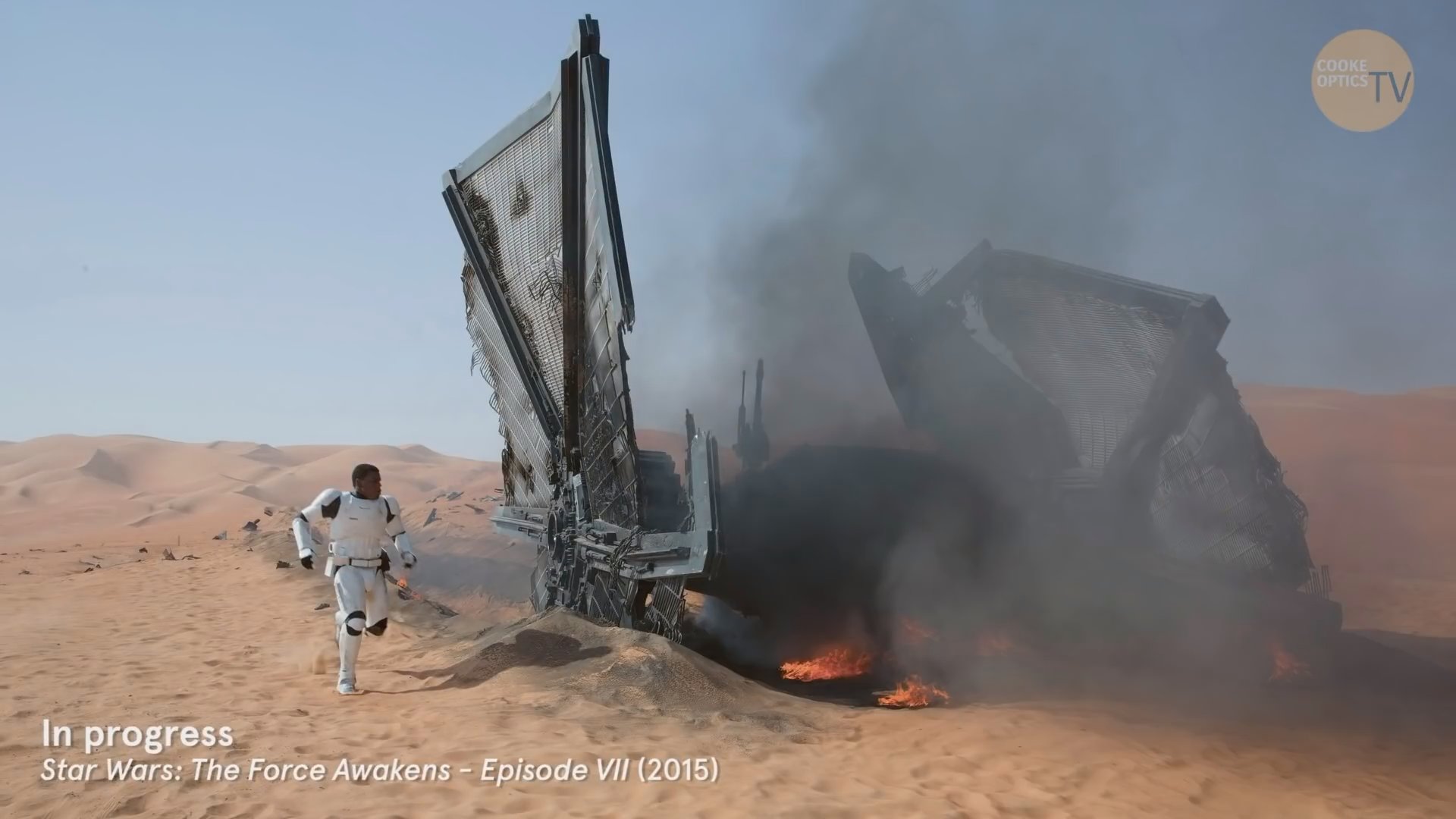
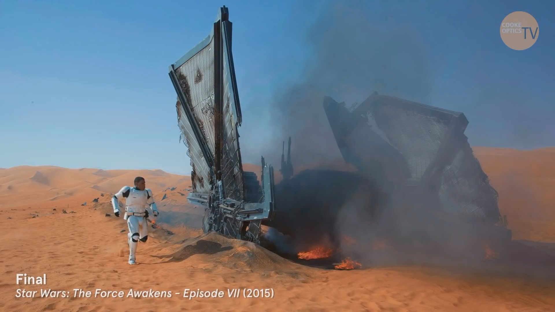
Most games, unlike films, leave the control of the camera to the player. That means that people working on films have the ability of tuning the camera position, materials and lighting of every shot. But having that ability doesn’t mean that they do. At one of the studios the lighters and some rendering engineers had the chance to spend a day in training with cinematographer Dan Mindel where he went over his work on Star Wars: The Force Awakens. He explained his approach tended to favor making lighting part of the set (meaning every shot doesn’t involve a unique mess of a lighting setup), being selective about the type of lights used, and working with the same colorist he has done for decades. He went over multiple scenes answering questions mostly from the lighters, and often the lighting setup was simpler than the questions implied. But avoiding overly complex setups didn’t result in a dull looking film.
 |
|---|
| Dailies color grade and final color grade. |
Conclusion.
On this console generation there has been many advances in real time rendering, but also limitations. On the geometry side there has been major advances such as more GPU-driven rendering, and virtualizing geometry, but not all content can leverage that. Progress is still being made when it comes to rendering foliage, crowds, and even dealing with aliasing and preserving appearance at a distance. On the material side most games built on generic engines (such as Unreal Engine, Unity and Frostbite) have been shipping with specialized fixed shading models that had to be implemented by hand by an engineer. In most cases a single shading model could be assigned per draw call. That means that horizontal layering (a transition from one material to another) isn’t possible without breaking up the geometry except for transitions using the same shading model. And because of the fixed nature of the shading models, it wasn’t possible to do arbitrary vertical layering (stacking of shading models) such as having a sweat layer using a standard dielectric shading model on top of skin with a subsurface scattering shading model. On the lighting side there have been major improvements on global illumination, but when it comes to direct lighting most games have been shipping with tiled or clustered deferred approaches which meant that careful management of lighting content continues to be a requirement.
But I think that within the timeline of the next generation of consoles, and through the work of many hardware and software engineers, many of those challenges will be more manageable or will be gone. Just like it has been happening since the 2010s, the key differentiators for immersive visuals on a game will come from the content rather than purely from engineering prowess. In that context, there are no indications that content will be less physically based. In fact, if anything, it seems like it will be more relevant as we are pushed for more reuse of content. On the geometry front, I think features like Nanite Displacement will become more pervasive, and features like Nanite Foliage will be generalized to all geometry and evolve to also preserve appearance. On the material side, generalized layering of BSDFs similar to Unreal’s Substrate or Unity’s Stacklit will be the norm and they will require more physically based values like F0 reflectance. And on the lighting front, the use of approaches like ReSTIR or MCMM will substantially increase the number of lights per pixel, extend the use of area lights, and improve the quality of the global illumination.
We are in a really challenging spot in our industry where games are taking a long time to make, and costs of production are high. Odds seem low that the amount of content will keep growing in the short term, but the expectation of quality of that content will keep going up. Assuming the game you are working on is within the AAA space, it isn’t enough to have a particular or unique art direction. You need to execute on that direction with a high level of craftsmanship. Creating and managing content in that context is very difficult, and the temptation is to cut corners and speed up the content creation. But that usually leads to compromising the quality of the content, which means compromising on the level of immersion for the player. But if you have solid foundations on how you create the content, then you are essentially cutting down the time it takes to go from concept art to an approved asset to put in game. Hopefully this post has provided some useful pointers to help you with the content creation.